NSDT工具推荐: Three.js AI纹理开发包 - YOLO合成数据生成器 - GLTF/GLB在线编辑 - 3D模型格式在线转换 - 可编程3D场景编辑器 - REVIT导出3D模型插件 - 3D模型语义搜索引擎 - AI模型在线查看 - Three.js虚拟轴心开发包 - 3D模型在线减面 - STL模型在线切割 - 3D道路快速建模
在前面的教程中,我们在虚幻引擎中添加了Perlin噪声,以便轻松地在代码/蓝图中复用。现在可以利用Perlin噪声来生成网格了。
1、RuntimeMeshComponent
经过一番研究,我发现了这个RuntimeMeshComponent,它可以在运行时生成网格(mesh),封装了一些底层的操作。
问题是,它仅适用于虚幻4.10-4.16,而我使用的是4.18。因此我决定为较新版本的虚幻引擎分叉并升级项目。
这个组件允许我们从一组顶点、三角形、法线等数据来生成网格。
2、什么是网格
用RuntimeMeshComponent生成网格需要以下信息:
- 顶点:构成网格的所有单个点
- 三角形:将顶点连接在一起以形成网格表面的三角形
- 法线:每个顶点的法向量。它们垂直于由其顶点形成的三角形,用于照明目的
- 切线:定义顶点纹理方向的 2D 矢量。
- UV:每个顶点的纹理坐标,介于 0 和 1 之间。
- 顶点颜色:每个顶点的颜色
让我们看一种非常简单的网格 — 由两个三角形组成的正方形:
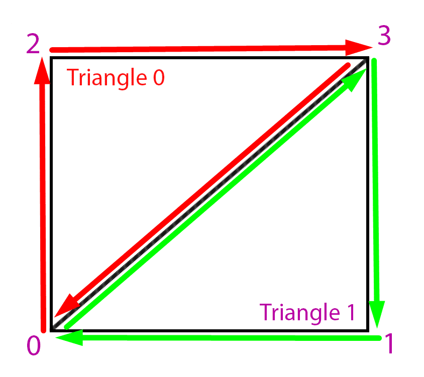
顶点次序是从左到右,从下到上,所以第一个顶点是左下角,然后是右下角,然后是左上角和右上角。
三角形由逆时针排列的三个顶点组成,因此我们可以使两个三角形组成这个方形网格:
- 三角形 0 :0 -> 2 ->3->0
- 三角形 1: 0 -> 3->1-> 0
3、在代码中生成顶点和三角形
在代码中,顶点和三角形被定义为数组:
- 顶点数组是向量数组。数组中的每个值都是一个 3D 矢量,表示顶点的位置
- 三角形数组是整数数组。数组中的每个值都是顶点数组的索引,该索引对应于三角形的点
例如,在我们的例子中(使用伪代码):
Array<Vector3> Vertices = (
	{0, 0, 0}, // Bottom left
	{1, 0, 0}, // Bottom right
	{0, 1, 0}, // Top left
	{1, 1, 0}  // Top right
)基于这些顶点的Triangles数组如下所示:
Array<int> Triangles = (
	0, 2, 3,
	0, 3, 1
);Triangles数组中的每个值都是Vertices数组中的一个索引。每组 3 个值形成一个三角形,所有三角形都是通过逆时针列出其顶点来定义的。
我们稍后将看到法线和其他参数,因为它们与网格生成没有直接关系。
4、用Perlin噪声生成顶点
为了生成我们的地形,需要大量的Perlin噪声值来制作一个像样的网格。
为简单起见,我们可以沿着栅格生成这些值。假设我们沿x和y方向每100个虚幻单位为单位采样一个Perlin噪声值。可以在二维循环中生成这些值:
UPerlinNoiseComponent* Noise; // A reference to our noise component
Noise = Cast<UPerlinNoiseComponent>(GetOwner()->GetComponentByClass(UPerlinNoiseComponent::StaticClass()));

TArray<FVector> Vertices;
int NoiseResolution = 300;
int TotalSizeToGenerate = 12000;
int NoiseSamplesPerLine = TotalSizeToGenerate / NoiseResolution;

// The number of vertices we'll have is the number of points in our [x,y] grid.
Vertices.Init(FVector(0, 0, 0), NoiseSamplesPerLine * NoiseSamplesPerLine);

for (int y = 0; y < NoiseSamplesPerLine; y ++) {
	for (int x = 0; x < NoiseSamplesPerLine; x ++) {
		float NoiseResult = Noise->GetValue(x + 0.1, y + 0.1, 1.0); // We have to add 0.1 because the noise function doesn't work with integers
		int index = x + y * NoiseSamplesPerLine;
		Vertices[index] = FVector(x * NoiseResolution, y * NoiseResolution, NoiseResult);
	}
}
此循环执行以下几项操作:
- 根据两个选项计算我们需要生成的点数,
NoiseResolution是两点之间的距离,TotalSizeToGenerate是希望网格的大小。 - 使用我们需要的点数初始化顶点数组
- 在 x 和 y 上循环以获取噪声值,并将它们添加到
Vertices数组中
现在这很好,但是这存在一些问题:
- 噪声输出值介于 -1 和 1 之间,这在我们的游戏中并不真正可见
- 我们无法控制噪声样本的距离
让我们为此引入一些设置,并稍微清理一下代码:
TArray<FVector> Vertices;
int NoiseResolution = 300;
int TotalSizeToGenerate = 12000;
int NoiseSamplesPerLine = TotalSizeToGenerate / NoiseResolution;

float NoiseInputScale = 0.01; // Making this smaller will "stretch" the perlin noise terrain
float NoiseOutputScale = 2000; // Making this bigger will scale the terrain's height

void GenerateVertices() {
	Vertices.Init(FVector(0, 0, 0), NoiseSamplesPerLine * NoiseSamplesPerLine);
	for (int y = 0; y < NoiseSamplesPerLine; y ++) {
		for (int x = 0; x < NoiseSamplesPerLine; x ++) {
			float NoiseResult = GetNoiseValueForGridCoordinates(x, y);
			int index = GetIndexForGridCoordinates(x, y);
			FVector2D Position = GetPositionForGridCoordinates(x, y);
			Vertices[index] = FVector(Position.X, Position.Y, NoiseResult);
			UV[index] = FVector2D(x, y);
		}
	}
}

// Returns the scaled noise value for grid coordinates [x,y]
float GetNoiseValueForGridCoordinates(int x, int y) {
	return Noise->GetValue(
		(x * NoiseInputScale) + 0.1,
		(y * NoiseInputScale) + 0.1
	) * NoiseOutputScale;
}

int GetIndexForGridCoordinates(int x, int y) {
	return x + y * NoiseSamplesPerLine;
}

FVector2D GetPositionForGridCoordinates(int x, int y) {
	return FVector2D(
		x * NoiseResolution,
		y * NoiseResolution
	);
}
这与以前的代码相同,但使用两个新的 scale 参数,并且重构为更清晰。
我们现在也分配UV只是为了有一些基本的纹理坐标,这将使我们的材质拼贴的纹理适用于每个四边形。
现在的噪声生成输出值都在[-1000,1000]范围内,这在虚幻引擎中应该更加明显。我们还可以缩放给定的值作为噪声的输入,这使我们能够拉伸或缩放地形(如果比例非常低,我们将获取非常接近的点,而如果比例很高,我们将获取相距很远且差异很大的点)。
5、生成三角形
现在,我们可以使用刚刚创建的顶点索引来生成三角形,进而生成四边形,每个四边形包含两个三角形(如上一个绘图所示)。
TArray<int> Triangles;

void GenerateTriangles() {
	int QuadSize = 6; // This is the number of triangle indexes making up a quad (square section of the grid)
	int NumberOfQuadsPerLine = NoiseSamplesPerLine - 1; // We have one less quad per line than the amount of vertices, since each vertex is the start of a quad except the last ones
	// In our triangles array, we need 6 values per quad
	int TrianglesArraySize = NumberOfQuadsPerLine * NumberOfQuadsPerLine * QuadSize;
	Triangles.Init(0, TrianglesArraySize);

	for (int y = 0; y < NumberOfQuadsPerLine; y++) {
		for (int x = 0; x < NumberOfQuadsPerLine; x++) {
			int QuadIndex = x + y * NumberOfQuadsPerLine;
			int TriangleIndex = QuadIndex * QuadSize;

			// Getting the indexes of the four vertices making up this quad
			int bottomLeftIndex = GetIndexForGridCoordinates(x, y);
			int topLeftIndex = GetIndexForCoordinates(x, y + 1);
			int topRightIndex = GetIndexForCoordinates(x + 1, y + 1);
			int bottomRightIndex = GetIndexForCoordinates(x + 1, y);

			// Assigning the 6 triangle points to the corresponding vertex indexes, by going counter-clockwise.
			Triangles[TriangleIndex] = bottomLeftIndex;
			Triangles[TriangleIndex + 1] = topLeftIndex;
			Triangles[TriangleIndex + 2] = topRightIndex;
			Triangles[TriangleIndex + 3] = bottomLeftIndex;
			Triangles[TriangleIndex + 4] = topRightIndex;
			Triangles[TriangleIndex + 5] = bottomRightIndex;
		}
	}
}现在有了可用的三角形就可以使用了。要生成实际的网格,我们只需要调用RuntimeMeshComponent的CreateMeshSection函数。
要在你的项目中安装RuntimeMeshComponent,请首先在Github上下载我的升级版本,然后按照这个教程进行安装,并参考这个教程将其暴露给C++代码:
// We need a reference to the runtime mesh
URuntimeMeshComponent* RuntimeMesh = Cast<URuntimeMeshComponent>(GetOwner()->GetComponentByClass(URuntimeMeshComponent::StaticClass()));
int VerticesArraySize = NoiseSamplesPerLine * NoiseSamplesPerLine;

// These other values will be seen in a later part, for now their default value will do
TArray<FVector> Normals;
TArray<FRuntimeMeshTangent> Tangents;
TArray<FVector2D> UV;
TArray<FColor> VertexColors;

Normals.Init(FVector(0, 0, 1), VerticesArraySize);
Tangents.Init(FRuntimeMeshTangent(0, -1, 0), VerticesArraySize);
UV.Init(FVector2D(0, 0), VerticesArraySize);
VertexColors.Init(FColor::White, VerticesArraySize);

void GenerateMesh() {
	RuntimeMesh->CreateMeshSection(0,
		Vertices,
		Triangles,
		Normals,
		UV,
		VertexColors,
		Tangents,
		true, EUpdateFrequency::Infrequent
	);
}

void GenerateMap() {
	GenerateTriangles();
	GenerateVertices();
	GenerateMesh();
}

GenerateMap();
将所有这些代码放在一个 actor 组件中,就可以通过将该组件提供给也具有PerlinNoiseComponent 和RuntimeMeshComponent 的组件来生成 地形。
本教程的完整TerrainComponent代码可以从Github下载。
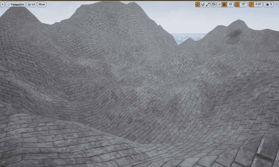
例如,如果将GenerateMap函数公开给蓝图,则可以通过以下方式创建地形:
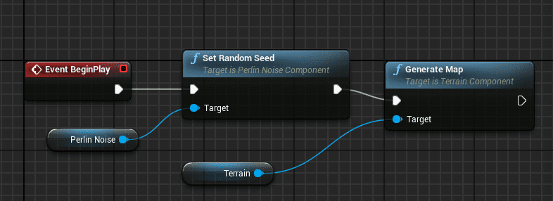
结果如下:
原文链接:Unreal Engine 4: Generating a procedural terrain with an underwater world (Part 2)
BimAnt翻译整理,转载请标明出处